AS9120B, ISO 9001:2015, and FAA AC 0056B Accredited
Posted on September 16, 2019 james smith aviation
Modern aircraft are made up of thousands of structural components, each of which must be precisely located for routine inspection, maintenance, and repair. Without a standardized method to reference where these components are situated, even simple tasks could become time-consuming and error-prone.
This is why aircraft location numbering systems were created, allowing every inch of an airframe to be mapped using consistent reference points. With these systems, technicians are able to communicate and work with accuracy, whether identifying a flap hinge point or a stringer deep within the cabin. In this blog, we will explain some important aircraft location numbering conventions, uncovering why they are so vital to safe and efficient maintenance practices.
FSs are numerical reference points measured in inches along the aircraft’s longitudinal axis. This starts from an origin point known as the reference datum, an imaginary vertical plane usually positioned at or near the tip of the aircraft’s nose labeled Station 0. All fuselage station measurements are taken from the reference datum, extending aft along the centerline of the aircraft.
Some manufacturers may refer to these as Body Stations (BS) instead of FS, but the principle remains the same.
The BL is a vertical reference plane that runs longitudinally along the aircraft’s exact centerline, used to measure lateral positions in inches to the left or right. By convention, positive BL values indicate positions to the right of centerline, while negative values indicate positions to the left.
Buttock lines are especially important for determining the precise lateral placement of structural elements such as wing attachment points, horizontal stabilizers, or landing gear assemblies.
The WL is a system of vertical reference points measured in inches above or below a designated horizontal plane on the aircraft. This plane often referred to as WL 0 may be aligned with the aircraft’s cabin floor, fuselage base, or another easily identified structure depending on its unique design.
Waterlines establish the height of structural components like bulkheads, stringers, and floor beams within the airframe. As such, these measurements enable technicians to maintain the structural symmetry of elements and uphold proper load distribution, especially in multi-deck aircraft where components are distributed across different elevations.
In addition to general fuselage measurements, aircraft manufacturers employ specific station numbering for key control surfaces and systems.
AS measurements begin at the inboard edge of the aileron and extend outward, perpendicular to the aircraft’s rear wing beam.
These values are for validating that the aileron is properly positioned relative to the wing structure.
KSs are used to determine the location of components along an aircraft's flap, ensuring accurate alignment. Like aileron stations, they are measured outboard from the inboard edge of the flap, extending perpendicularly from the wing’s rear beam.
NC measurements are employed to locate structural elements within or around the engine nacelle, such as mounts and cowlings. These measurements are taken forward or aft of the front spar of the wing, and are aligned perpendicular to a designated waterline within the nacelle area.
On larger or more complex aircraft, several additional reference designations may be used, including:
In summary, aircraft location numbering systems are essential for enabling precise identification, communication, and servicing of structural components. However, for maintenance tasks to be carried out with the utmost accuracy and safety, it is just as imperative to source high-quality parts that meet rigorous performance standards. ASAP Semiconductor is proud to support these needs through its online platform, Aviation Sourcing Solutions.
With access to an extensive inventory of aircraft structural parts and more, all of which are sourced from leading global manufacturers and suppliers, this website makes it easy to secure all of the components you require in one convenient place. In addition to our commitment to quality and compliance, we offer competitive pricing, rapid lead times, and tailored solutions to ensure seamless fulfillment. If you would like to learn more about how we can support your specific procurement needs, connect with one of our knowledgeable team members at your convenience.
Share
![]()
![]()
![]()

 The only independent
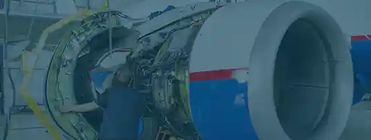


“We Proudly Support Intrepid Fallen Heroes Fund that serves United States Military Personal experiencing the Invisible Wounds of War : Traumatic Brain Injury (TBI) and Post Traumatic Stress (PTS). Please visit website (www.fallenheroesfund.org) and help in their valiant effort”.
We Hope that You Will Visit Us Again the Next Time You Need Aircraft Parts and Make Us Your Strategic Purchasing Partner.
Request for Quote